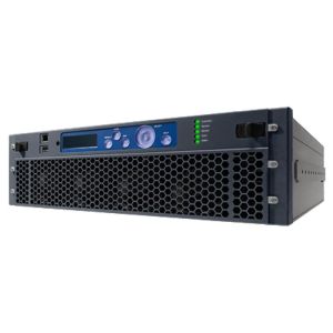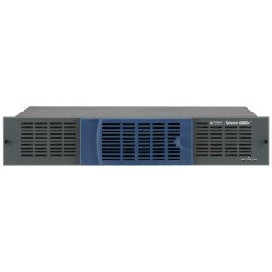


Imagine SEL-DDA1-EES DUAL DA, D TO A, HD-BNC IN/OUT; Dual...
Imagine SEL-DDA1-EES DUAL DA, D TO A, HD-BNC IN/OUT; Dual Distribution Amplifier (SDI/ASI) and Dual Digital (SDI 270 Mb/s) to Analog (NTSC, PAL) module with routing capability, includes back module with HD-BNC inputs and outputs
Dual Distribution Amplifier (SDI/ASI) and Dual Digital (SDI 270 Mb/s) to Analog (NTSC, PAL) module with routing capability, includes back module with HD-BNC inputs and outputsThe Selenio SEL-DDA1-xxx provides multiple functions. Conversion from SDI (270 Mb/s) to analog composite (dual channels) adds NTSC/PAL and PAL-M outputs to the Selenio platform. The DDA can be used as a single / dual distribution amplifier, small routing switcher SDI / ASI and electrical fiber optic converter. If placed beside a Selenio frame sync (FS) or conversion (XD), the DDA may be used as a VEX video expansion module.
Features
- Dual D to A conversion
- Single/Dual SDI/ASI DA function
- Single/Dual SDI/Monitoring DA function (for SD)
- Small SDI/ASI routing switcher function
- Optional relay bypass (dual-channel capability)
- Optional SFP for optical input and output
- Optional MAGELLAN remote panels for control and monitoring
Details
The DDA may be placed in any open Selenio slot and has its own block diagram User Interface.
If used as a VEX, it must be installed beside a frame sync or video conversion applications module and will automatically be connected. When viewing the front of the frame, the DDA is placed to the left of the FS/XD applications module (lower slot number). The block diagram in the FS or XD User Interface is updated giving the user setup, control and monitoring functions. Five back module options provide interfaces for electrical and optical inputs and outputs and relay bypass for critical signals upon power loss — one with HD-BNC electrical connections for input and output; one with HD-BNC electrical connections for input and output and dual relays; one with a dual SFP optical input with HD-BNC outputs; one with HD-BNC inputs with two dual SFP optical outputs; and one with a dual SFP optical input and two dual SFP optical outputs.
SDI interfaces utilize a Belden-type 1505A, 1694A or 1695A cable (or equivalent) with HD-BNC connectors. HD-BNC to BNC adaptor cables and a cable insertion/removal tool are available for the HD-BNC connections.
Adding Analog Composite Outputs to the Selenio Platform
The DDA’s primary function is to add two analog composite outputs per DDA module to the Selenio platform. Within the DDA, it is possible to convert one or two 270 Mb/s SDI (electrical or optical) externally connected or one internally connected (any slot in the frame) to two analog composite outputs. For HD down conversion to analog composite output, the XD module is required.
SDI/ASI Distribution Amplifier Function
The DDA can be setup to operate as a single or dual channel SDI or ASI distribution amplifier.
SDI/ASI Small Routing Switcher
The DDA can be setup to operate as a small routing switcher for SDI or ASI.
Electrical/Optical Interface
The DDA can be used as a single or dual channel electrical to/from optical interface.
Input to Output Summary Table
| SDI/ASI DA | SFP | |||
|---|---|---|---|---|
| Inputs | Outputs | Inputs | Outputs | |
| SEL-DDA1-REL | 2 | 6 | 0 | 0 |
| SEL-DDA1-EES | 2 | 8 | 0 | 0 |
| SEL-DDA1-EES and SEL-BM-VEXDDA-EOS | 2 | 4 | 0 | 4 |
| SEL-DDA1-EES and SEL-BM-VEXDDA-OES | 0 | 7 | 2 | 0 |
| SEL-DDA1-EES and SEL-BM-VEXDDA-OOS | 1 | 2 | 2 | 4 |
| All input to output connections are user selectable | ||||
Relay Bypass
As well, for critical paths to pass program signals upon loss of power, relay bypass is a requirement. The DDA supports a version for dual replay bypass for SDI upon loss of power.
The DDA can be used to provide a “passive loop through for the ENC module” by taking the program signal into DDA bypass relay input and then taking the program signal from the bypass relay output to wherever it is needed in the system design and one of the active outputs can feed the input of the ENC.
MAGELLAN remote control panels can be set up to access all parameters for Selenio processing modules. The panels with an OLED display and rotary control add the capability to make adjustments with the rotary control and view the parameter changing and view status parameters.
Specifications
Specifications and designs are subject to change without notice
| SDI Input | |
|---|---|
| Number of Inputs | 1 (-OOS back module) 2 (-EES, -REL, and -EOS back modules) |
| Standard | 1080p (SMPTE 424M) 3G HD-SDI 1080i/p (SMPTE 292M) HD-SDI 720p (SMPTE 296M) HD-SDI 525/625 component (SMPTE 259M-C, 270 Mb/s) SD-SDI |
| Frame Rate | 1080i/p/psf: 23.98, 24, 25, 29.97, 30, 50, 59.94, 60 Hz 720p: 50, 59.94, 60 Hz 525/625 |
| Connector | (High-Density) HD-BNC |
| Impedance | 75 ohms |
| Return Loss | >15 dB to1485 MHz >10 dB from 1485 to 2790 MHz |
| Equalization | 3G: Adaptive cable equalization for up to 459 ft (140 m), typical, of Belden 1694A coaxial cable; 328 ft (100 m) for SEL-DDA1-REL version, typical** HD: Adaptive cable equalization for up to 656 ft (200 m) typical, of Belden 1694A coaxial cable; 524 ft (160 m) for SEL-DDA1-REL version, typical** SD: Adaptive cable equalization for up to 984 ft (300 m) typical, of Belden 8281 coaxial cable; 1,312 ft (400 m), typical, of 1694A Belden 1694A coaxial cable** |
| * Support for SMPTE 372M Level B | |
| **Relay bypass HD-BNC connectors are excluded from these equalization specifications. When in bypass mode, the module’s equalization depends on the sensitivity of the downstream device connected to the output of the Selenio DDA relay output. The module equalizes the total length of the sum of the input and output cables that connected to the relay by-passable HD-BNC connectors. | |
| The DDA1 and VEX1 use an extended 3G-reach equalization. When combined with Belden 8281 coaxial cable, a pathological pattern, and a non-SPMTE424 (6.1.7)-compliant signal with excessive output amplitude excursions, the source equalization may be reduced to between 200 and 300 m for SD-SDI signals. This condition typically only occurs with older SD-SDI equipment having a 1uF capacitor on the output. All recent and multi-rate SD/HD/3G equipment is compliant with the standard (having at least a 4.7uF capacitor on the output), and can achieve 300 m with 8281 cable and pathological pattern. | |
| 3G/HD/SD-SDI Output Video | |
|---|---|
| Number of Outputs | 2 (-OOS back module) 4 (-EOS back module) 7 (-OES back module) 8 (-EES and -REL back modules) |
| Standard | 1080p (SMPTE 424M) 3G HD-SDI 1080i/p (SMPTE 292M) HD-SDI 720p (SMPTE 296M) HD-SDI 525/625 component (SMPTE 259M-C, 270 Mb/s) SD-SDI |
| Frame Rate | 1080i/p/psf: 23.98, 24, 25, 29.97, 30, 50, 59.94, 60 Hz 720p: 50, 59.94, 60 Hz 525/625 |
| Connector | (High-Density) HD-BNC |
| Impedance | 75 ohms |
| Return Loss | >15 dB to1485 MHz >10 dB from 1485 to 2790 MHz |
| Signal Level | 800 mV ±10% |
| DC Offset | 0.0 V ±0.5 V |
| Rise and Fall Time | 3G: <135 ps HD-SDI: <270 ps SD-SDI: 400 to 1500 ps |
| Overshoot | <10% |
| Jitter | Timing jitter: 3G HD-SDI: <2 UI pk-pk (>10 Hz) HD-SDI: <1 UI pk-pk (>10 Hz) SD-SDI: <0.2 UI pk-pk (>10 Hz) Alignment jitter: 3G HD-SDI: <0.3 UI pk-pk (>100 Hz) HD-SDI: <0.2 UI pk-pk (>100 Hz) SD-SDI: <0.2 UI pk-pk (>1 kHz) |
| SDI Fiber | ||||
|---|---|---|---|---|
| OP+SFP+RR Dual Input Fiber | ||||
| Item | Minimum | Typical | Maximum | Note |
| Number of LC Input Connectors | - | - | 2 | |
| Input Wavelength | 1260 nm | - | 1620 nm | |
| Optical Power Monitor Accuracy | -2 dB | - | -2 dB | |
| Sensitivity at 270 Mb/s (SMPTE 259M) | - | -22 | -20 | Pathological* |
| Sensitivity at 1.5 Gb/s (SMPTE 292M) | - | -22 | -20 | Pathological |
| Sensitivities at 3 Gb/s (SMPTE 424M) | - | -20 | -18 | Pathological |
| Overload | 0 dBm | - | - | 2.97 Gb/s* |
| *BER = 1E-12 against SDI matrix. Check field signals for video applications. BER = 1E-12 against PRBS 223-1 for datacom applications. | ||||
| OP+SFP+RR Dual Input Fiber | ||||
|---|---|---|---|---|
| Item | Minimum | Typical | Maximum | Note |
| Number of LC Connector Outputs |
2X2 | |||
| Standards | 3G: SMPTE 424M HD: SMPTE 292M SD: SMPTE 259M | |||
| Peak Wavelength | 1280 nm | 1310 nm | 1340 nm | Measured at 25C |
| Spectrum Width (RMS) | - | 1.5 nm | 3 nm | |
| Average Output Power | -5 dBm | -2 dBm | 0 dBm | |
| Optical Rise/Fall Time (3G HD-SDI) | 105/120 ps | 165/180 ps | ||
| Extinction Ratio | 7 dB | - | - | |
| Jitter | - | 45 ps | 70 ps | 3 Gb/s Pathological |
| - | 60 ps | 100 ps | 1.5 Gb/s Pathological | |
| - | 110 ps | 180 ps | 270 MHz Pathological | |
| Laser Safety Level | Class 1 | |||
| Composite Video Output | |
|---|---|
| Standard | NTSC (SMPTE 170M) PAL-B (ITU 624-2) PAL-M (ITU-R BT.470-6) |
| Connector | (High-Density) HD-BNC |
| Quantization | 12 bits |
| Impedance | 75 ohms |
| Return loss | >40 dB (0.1 to 6 MHz) |
| Frequency response | ±0.2dB, typical (0.1 to 6 MHz) |
| DC offset | <0.0 ±0.005 V |
| Differential gain | <0.5% |
| Differential phase | <0.5 |
| Y/C delay | <10 ns |
| Transient response | <0.5% K Factor |
| SNR | >63 dB typical (luma ramp) (0.1 to 6 MHz) >80 dB typical (Flat field) |
| Module Power Consumption | 40 W maximum |
| Manufacturer | Imagine Communications |
|---|