


Thor GPS over Fiber - F-1GPS-Tx-WE
The Thor Fiber GPS over Fiber outdoor weather kit allows you to send a GPS signal over long distance for synchronizing cellular base stations.
Allows transmission of the two main signals in the GPS band, L1 and L2, at 1575.42 MHz and 1227.6 MHz.
By usin
Manufacturer: Thor Broadcast
$2,995.00
Availability: In stock
SKU
F-1GPS-Tx-WE
Manufacturer: Thor Broadcast
Thor GPS over Fiber - F-1GPS-Tx-WE
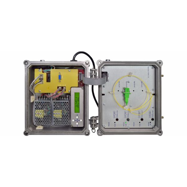
The Thor Fiber GPS over Fiber outdoor weather kit allows you to send a GPS signal over long distance for synchronizing cellular base stations. Allows transmission of the two main signals in the GPS band, L1 and L2, at 1575.42 MHz and 1227.6 MHz. By using built-in LNA , this GPS over Fiber Link is designed to offer a very low noise figure Sending GPS over the coax is very dificult to do over long distances so our GPS system has many diferent advantages: Units have LCD dispalys to display RF and Optical levels that is built into our units The transmitter shows incoming RF level and optical output power. The receiver has built in Optical power meter and RF ouput level meter, allows simple troubleshooting. Thransmitter is waterproof and Receiver is rackmountable in 1RU chassis. The Transmitter has Bios-T and can power Active GPS antena. Both transmitter and receiver have dual redundant power supplies, making them very robust and pragmatic for commerical architectures. These systems are very easy to deploy and can offer various configurations very many applications. Main receiver is 19' rack mountable but tranmitter has a built in compact enclosure which is deployable in any environment. Units are used as a point to point transmission from the tramsitter to the receiver, but the transmitter can be accompanied with our optical splitters which can be used for point to multipoint applications (star configuration) 1x2, 1x4, 1x8 ,1x16 and 1x32 It's also possible to add additional splitters on the receiver side and have up to 6 GPS ouputs on the receiver (special order). You can add 1x2 optical splitters to the receiver and use them as in line from one receiver to the next in a cascading configuration for easy distribution.
Features:
- Supports both GPS bands, L1 and L2, at 1575.42 MHz and 1227.6 MHz
- Waterproof Transmitter - NEMA 4 Fiber Transmitter for outdoor weather enclosure
- 19" rack mountable receiver
- 50 ohm TNT connector or N type by request
- +5V DC to the GPS antena
- Dual power supplies
- Optical meter built in
- RF meter built in
- RS232 communication and setup
- SC/APC fiber connectors
- Transmitter supports up to 32 Receivers
- Transmits all common GPS, GALILEO and GLONASS bands
- L1 and L2 GPS frequencies
- Link operation 1m to 50km
- >50km systems also available
- GPS antenna powering and monitoring
- DAS, WiMax, Satcom, LTE
Specifications:
- GPS FIBER TRANSMITTER
- Optical Characteristics
- Laser Type - DFB, Optical Wavelenght nm 1310 or (CWDM 1510,1530,1550,1570nm -Special order)
- Optical Output Power - mW 1 or ( 2,3,4,8 -Special order)
- Optical Return Loss - dB 50
- Optical Connector Type - SC/APC
- RF Characteristics
- Input Impedance - Ω 50
- RF Connector - BNC Type
- Working Bandwidth - MHz 85~2000
- Input Range - dBuV 47~67
- Input level (AGC attenuation=0)
- Flatness - dB ±2 50~2000MHz
- Input Return Loss - 12dB 50~2400MHz
- C/IM3 - ≥55
- Note 1 (Note 1: C/IM3 is defined as the ratio between the peak of carrier signal and triple beat (IM3) by using a two-tone test (1.0GHz and 1.1GHz).
- AGC attenuation - dB -7~+7
- Note 2: The test condition adopts the specified optical transmitter, AGC attenuation= 0 and optical receiving power= -5dBm.
- General Characteristics
- Serial Interface - RS232
- Power Supply (AC) - V 100~240
- Optional dual power (Special Order)
- Consumption - W 10
- Relative Humidity - 5~95%
- Working Temperature - °C -20~60
- Storage Temperature - °C -40~70
- Dimension (W)*(D)*(H) - (10x10x6.5)inches
- GPS FIBER RECEIVER
- Optical Characteristics
- Laser Type - DFB
- Optical Wavelength - nm 1260-1620
- Optical Return Loss - dB 50
- Optical Connector Type - SC/APC
- RF Characteristics
- Input Impedance - Ω 50
- RF Connector - BNC Type
- Working Bandwidth - MHz 85~2000
- Input Range - dBuV 47~67
- Input level - (AGC attenuation=0)
- Flatness - dB ±2 @ 50~600MHz and also dB±1.5 @ 600~2000MHz
- Input Return Loss - dB 12 @ 50~2400MHz
- C/IM3 - ≥55 ---Note 1: C/IM3 is defined as the ratio between the peak of carrier signal and triple beat (IM3) by using a two-tone test (1.0GHz and 1.1GHz)
- AGC attenuation - dB -7~+7 ---Note 2: Note 2: The input level range is 47~67dBµV when AGC attenuation=0; the input level range is 48~68dBµV when AGC attenuation=1. That is to say, AGC attenuation increase 1dB, the input level will corresponding increase 1dB and the optical receiver output level will also increase 1dB (the same optical power received). The reduce rule is just the same.
- General Characteristics
- Serial Interface - RS232
- Power Supply (AC) - V 100~240
- Optional dual power (Special Order)
- Consumption - W 10
- Relative Humidity - 5~95%
- Working Temperature - °C -20~60
- Storage Temperature - °C -40~70
- Dimension (W)*(D)*(H) - 1U 19 inch (19x114x3)
Manufacturer: Thor Broadcast
| Manufacturer | Thor Broadcast |
|---|
Write Your Own Review


My Wish List
Last Added Items
You have no items in your wish list.